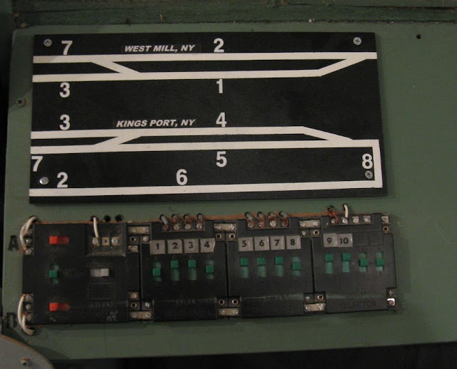
I was originally planning to continue presenting my Penn Central locomotive roster in this next post, but am instead going to talk about a signal project I've been working on lately.
Look Ma! No toggle switches! :)
So, no electronically controlled switch machines, no illuminated structures, and no functioning signals on my layout.
Last year, however, I DID create a large scale model of a railroad signal for fun, and to use while operating the layout from my F unit control stand.
Here's a YouTube video of it in action:
https://www.youtube.com/watch?v=PfjQu-3ayYY
If you watched the video, you saw that I have some nonfunctioning signals that can be seen as "dark" from my train cam. One of the motivations to illuminate some of these was the thought of enjoying red and green lights coming into view on my TV/ locomotive windshield as my loco with the train cam approaches them.
I've done numerous searches about model railroad signal systems but most are rather expensive and I don't immediately grasp the concepts of "logic" that control them. Fortunately one of my searches found a link to inexpensive scratchbuilt signals used to indicate the track polarity. Utilizing bi polar red/green LEDs, these signals wired to the track let the operator know which direction trains will run. It occurred to me that I could use an indicator like that for a staging track at West Mill. Using two throttles, I sometimes lose track of the direction a train might take when powering up. Trains might appear on the layout from staging OR they might back up against the bumper of the staging track, and derail in the hidden depths, creating a major headache.
I purchased a package of five bi polar LEDS around three years ago and finally got around to trying my hand at working with the lights. Soldering the accompanying resistor and some wire to one of the LEDs was easy. I used a cheapie Bachmann dwarf signal as the basis for the model. Drilling out one of the facsimile lights in the signal I inserted the LED in the back and used a thin plastic coffee stir straw to hide the resistor and wire. (Cue dramatic Frankenstein movie music). IT WORKS!!!!!!! IT WORKS!!!! Thank you for your indulgence in response to my first small but significant victory in working with LED technology!
Green signal means its OK to to run a train into staging. Red means its OK to run one out of staging.
Once I got my feet wet, I wanted to try more LED signal projects. The next obvious choice was the empty signal bridge by West Mill's tunnel. The two tracks that disappear into the tunnel are the layout's continuous main line and a long siding that emerges with the main on the other side of the layout at King Port. Since during operations I use the hidden section of both of these tracks as staging it was also important to be confident about the directions trains will travel when I hit the throttle.
I soldered resistors and wire leads for three
LEDs, one for the main and two to control the siding and the turnout
from the main to the siding.
I'm using grommets as the signal heads, cutting half of the protruding part to simulate a "hood" or shade for the light.
I threaded the wires through black stir straws and the bases of the signsl bridge uprights, guided them through holes in the bench work, and soldered them to the tracks. Briefly using alligator clips to attach the six wires, trial and error sessions enabled me to determine the proper locations to solder the wires so the LEDs would show the proper aspects (I.e. Green for "approach toward the tunnel" and red for "Stop...trains are coming out of the tunnel")
Once again...IT WORKS!!!!!!!
Things I learned: I don't have to connect the resistor directly to the LED. Doing so with all thee LEDs on the signal bridge left a lot of bulky items to cover up that could have been below the benchwork. I also realized later that I could have wired the two LEDs that control the siding (the two lower level signals) as part of the same circuit instead of separately each with its own resistor.
Still, as my most sophisticated electrical project so far, I'm pleased with the results and look forward to learning more and creating additional lighting effects!
May you always have the green aspect!


